









Send Us A Message
How to Choose a Straining Extruder by Compound Viscosity and Screen Size
Start with the compound, not the nameplate throughput. A straining extruder that performs well on a soft, clean compound can become pressure-limited, unstable, or difficult to clean when the same line receives a colder, higher-viscosity batch or a finer screen pack. The selection point is the operating window formed by compound viscosity, contamination load, required screen opening, temperature control, and the acceptable pressure range of downstream equipment.
Capacity remains important, but quoted output is meaningful only when the test compound, screen configuration, and discharge conditions are known. For a reliable selection, define the material condition at the extruder inlet and evaluate whether the machine can maintain a stable discharge rate as the screen gradually loads.
Read Compound Viscosity as a Process Condition
Viscosity is not a single fixed material value in extrusion. It changes with compound formulation, filler level, polymer grade, moisture, batch temperature, storage history, and shear generated in the screw. Two compounds described as similar may therefore produce very different pressure behavior through the same screen pack.
A low-viscosity compound passes through a given mesh with less resistance. This may permit a smaller screen opening or a higher rate, but it also makes temperature control important: excessive shear heating can change flow behavior and affect the condition of the discharged strip. A high-viscosity compound requires more torque and develops higher head pressure before it reaches the screen. If the extruder is selected only by nominal output, the machine may run near its pressure or drive limit whenever a colder batch arrives.
Request the viscosity information in the form actually used by the process, together with the expected feed temperature range. Also establish whether the compound is supplied as strips, slabs, pellets, or pre-mixed material. Feed geometry affects bite, screw filling, and the consistency of material transfer into the screening zone. A machine that has adequate motor power may still show unstable output if the feed system cannot present a uniform material charge.
Separate Shear Heating from Screen Restriction
Rising discharge temperature and rising pressure often appear together, yet they do not always have the same cause. A restrictive screen pack creates pressure upstream of the breaker plate. High internal shear caused by screw design, speed, or restricted flow passages raises material temperature more directly. Increasing cooling water flow can mask a heat issue but will not remove the pressure loss created by a fine or clogged screen.
During evaluation, compare pressure, melt or stock temperature, drive current, and output over a sustained run. A gradual pressure increase at largely stable temperature often points to screen loading. A rapid temperature rise with increasing drive current may indicate excessive shear, poor cooling contact, or an unsuitable screw profile for the compound. These observations lead to different corrective actions and should not be treated as a single “high-pressure” condition.
Choose Screen Size by the Defect You Need to Remove
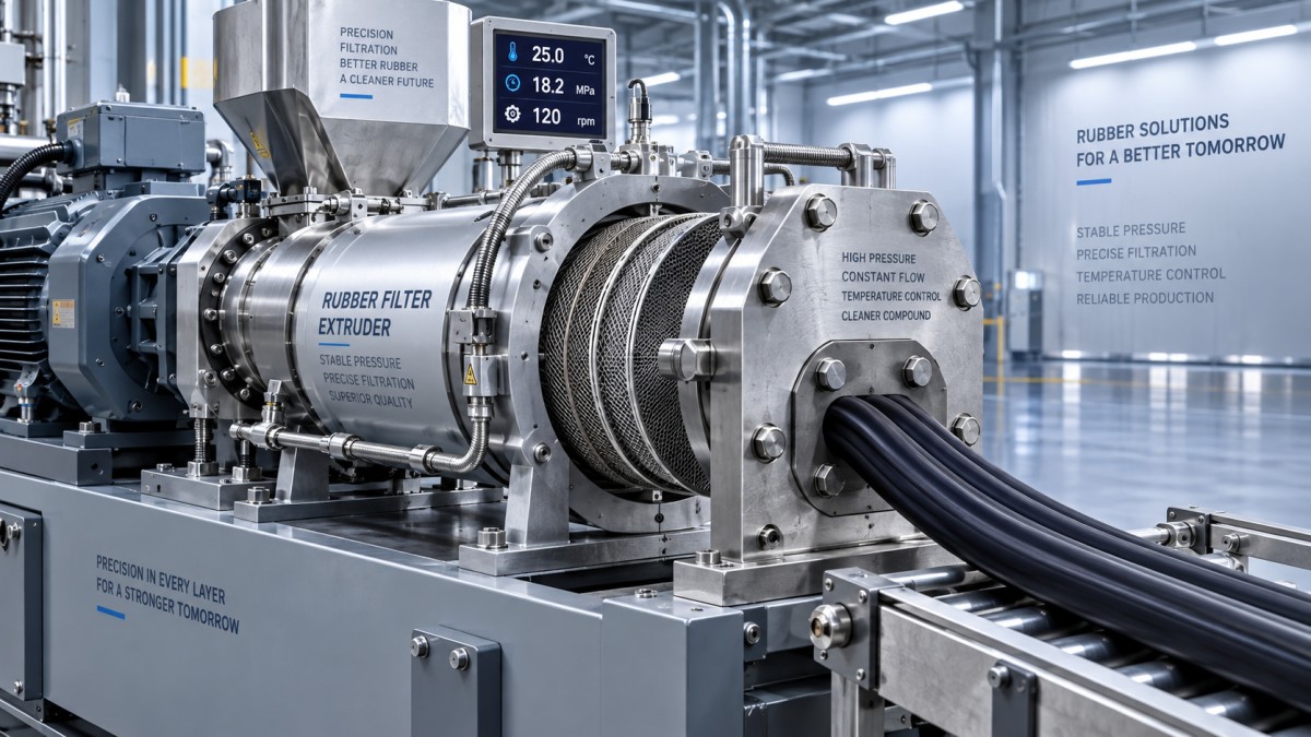
Screen size should be linked to the contaminant or unmixed material that creates the actual quality risk. A finer screen does not automatically produce a better result. It captures smaller particles, but it also reduces open area, increases pressure drop, and shortens the useful interval before the screen requires replacement. The screen pack must remove unacceptable foreign matter, hard gel, scorch particles, or coarse unmixed fragments without creating an operating condition that damages the compound or interrupts the line too frequently.
Screen designation alone is incomplete. Wire diameter, weave type, effective open area, screen diameter, and the number of layers all affect resistance. A fine working screen supported by several heavy backing layers can behave very differently from a single screen of the same nominal mesh. Ask for the complete screen-pack arrangement used to establish the proposed output rating.
The breaker plate also deserves attention. Its hole pattern must support the screen without creating unnecessary stagnant zones. Poorly supported screens can deform under pressure, allowing bypass or changing the effective filtration path. Areas that retain compound during shutdown can later release degraded material into a new batch.
Match the Extruder Configuration to the Pressure Profile
For higher-viscosity compounds or tighter filtration, the screw, barrel, drive, and head must be considered as one pressure system. A larger screw diameter does not automatically solve the problem. It may increase output, but the required head pressure still depends on the screen pack and compound flow characteristics. Conversely, a small machine operating at elevated screw speed can generate excessive shear even when its calculated throughput appears sufficient.
Specify a usable operating range rather than a single target rate. The selected straining extruder should maintain the required output at the upper expected compound viscosity and at a screen condition representing normal loading, while retaining room for ordinary batch variation. The drive should be assessed by continuous torque capability, not only peak power. Peak capability is useful during start-up or a temporary disturbance; it is not a basis for routine operation.
Temperature zones should be independently controllable where the process requires it. Barrel cooling, screw cooling, and head temperature management have different effects. Strong cooling at the barrel can improve control but may also raise viscosity locally and increase torque. Uniform thermal behavior is more valuable than pursuing the lowest possible discharge temperature without regard to pressure stability.
Screen Changing Is Part of the Selection
A screen pack eventually loads, even when incoming material is well controlled. The practical question is how the machine behaves before and during replacement. For frequent changes, a design that permits safe, repeatable access to the head and breaker plate reduces variation caused by inconsistent reassembly. The head should be evaluated for access clearance, lifting requirements, sealing surfaces, and the time needed to return to stable pressure after a change.
Continuous or automatic screen-changing arrangements can reduce interruptions where contamination is frequent or production cannot tolerate a stop. They introduce their own process requirements: transition flow, dead-volume control, pressure sensing, and maintenance of moving sealing components must all be understood. For clean, stable compounds with planned production intervals, a simpler manual arrangement can be easier to validate and maintain.
Use a Trial That Represents Real Material Variability
A meaningful acceptance trial uses production-representative compound, not only a convenient soft batch. Include the colder end of the expected feed range and, where relevant, material containing the typical level of reclaim, filler variation, or residual contamination. Run long enough for the screen to begin loading. A short test with a fresh screen mainly shows initial flow resistance and may conceal the operational limit.
- Record inlet condition, screw speed, output, pressure before the screen, discharge temperature, and drive load at regular intervals.
- Inspect strained material for retained particles, surface consistency, and evidence of thermal degradation or unstrained bypass.
- After shutdown, inspect the breaker plate and head for retained compound, damaged screens, distorted support layers, and uneven flow marks.
- Compare results at the intended screen pack and at the finest pack likely to be required; the equipment choice should not depend on an unrealistically open screen.
Where the equipment will be installed near steel fabrication or maintenance areas, the preparation of structural members can affect contamination control around the extrusion line. Surface-treatment equipment such as Mobile type shot blasting machines is relevant to that broader housekeeping boundary, but it does not replace feed-material inspection or screen selection inside the rubber process.
Resolve the Common Specification Gaps
Several purchasing documents state a capacity and a mesh number but omit the information that determines whether those values are achievable. Clarify the compound feed temperature, required screen diameter, full screen-pack construction, pressure measurement location, discharge form, allowable temperature rise, and whether the quoted rate is continuous or intermittent. Include the expected screen-change method and the maximum practical change interval for the line.
Do not interpret persistent high pressure as proof that a finer screen is working effectively. A blocked screen, inadequate open area, degraded compound, a cold feed batch, or a restricted downstream die can all produce similar gauge readings. Trace the pressure path and inspect the discharged material before changing mesh size or increasing screw speed.
The strongest selection is the one that holds filtration quality within a controlled pressure and temperature range when compound behavior changes. That balance keeps screen size tied to the actual defect requirement and prevents nominal capacity from becoming the only basis for equipment choice.