










Send Us A Message
Safety Checks for Vacuum Forming Machines With High-Temperature Heaters
A vacuum forming machine with high-temperature heaters should not enter production until its thermal, electrical, and motion-related safeguards have been verified as a connected system. A heater bank may appear to reach the programmed setpoint while still creating unsafe hot spots, unstable sheet heating, exposed live parts, or a delayed emergency stop response. These conditions affect both injury prevention and forming consistency: a sheet that is overheated at one edge can sag into guarded areas, release fumes, stick to tooling, or create thin sections that are discovered only after trimming.
The most reliable starting point is the machine’s cold condition. Before heater power is enabled, inspect the heater frame, reflectors, ceramic supports, terminal covers, and insulation for discoloration, cracks, loose hardware, or distortion. Darkened reflectors and brittle insulation are not merely cosmetic findings. They can indicate prolonged overheating, poor airflow, or a failed heating element that has forced adjacent zones to work harder.
Examine the Heater Field, Not Only the Displayed Temperature
A controller display confirms the value received from a sensor; it does not prove that the entire heating field is uniform. A temperature sensor can remain within tolerance while a damaged element, contaminated reflector, or partial wiring fault produces an excessively hot or cold area elsewhere in the heater bank. This distinction matters most when forming thin-gauge sheet, dark materials, recycled-content sheet, or materials with a narrow processing window.
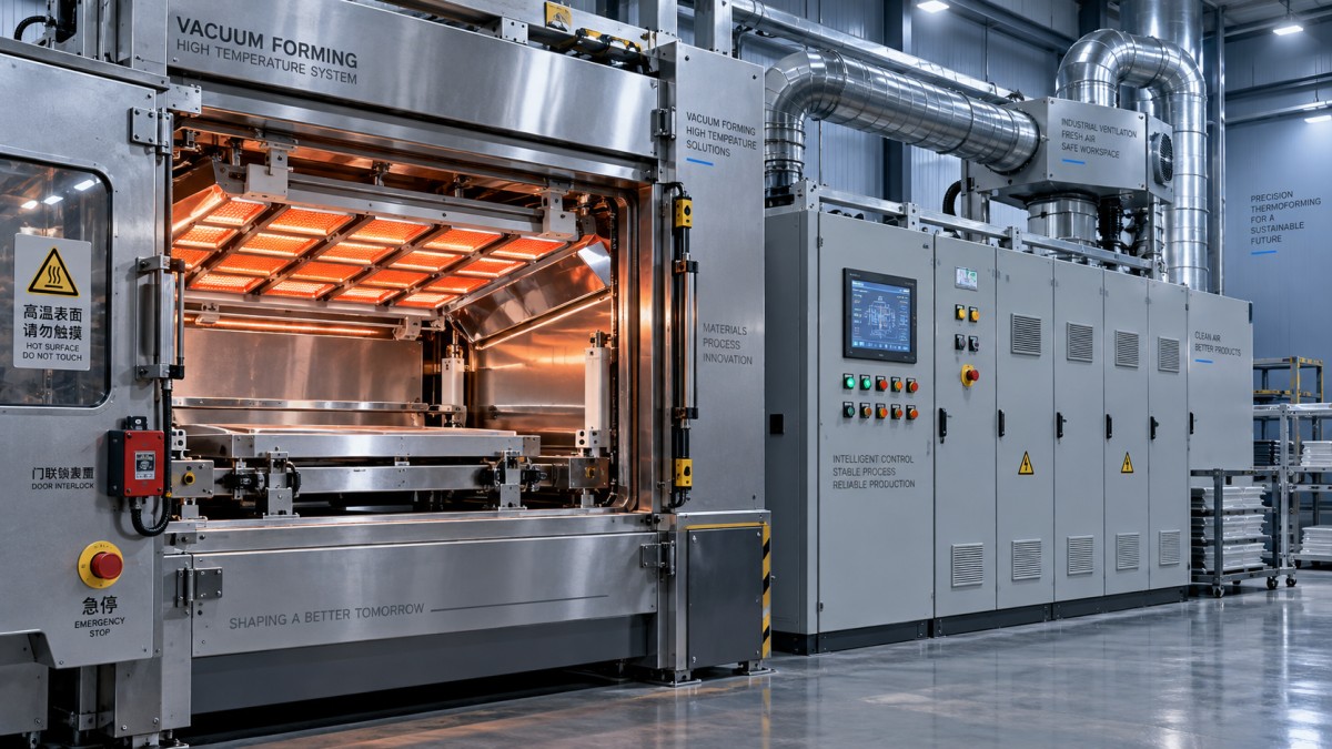
Start with a visual comparison of all active zones during warm-up. Elements should heat in a consistent pattern appropriate to the selected recipe. A zone that remains visibly dim, heats later than neighboring zones, cycles unusually often, or stays energized after the controller calls for heat needs investigation before a production run. Do not judge an infrared heater solely by apparent brightness; viewing angle, reflector condition, and element type affect how it looks. Compare the observed pattern with the commanded zones and with the sheet response.
Where site procedures permit, use a suitable temperature verification method to compare selected locations across the heater field. Surface readings require care because emissivity varies by material and finish. A shiny metal reflector, black heater surface, and plastic sheet do not produce equally reliable readings with the same instrument setting. A trend showing one zone consistently different from adjacent zones is more useful than treating one isolated reading as proof of uniform heating.
Control Stability and Over-Temperature Protection
Verify that the temperature recipe matches the material, sheet thickness, and tooling cycle rather than reusing a familiar setting without review. Heater temperature alone does not define the thermal load on the sheet. Distance between heater and sheet, dwell time, preheat stage, sheet color, moisture condition, and reflector cleanliness all alter the absorbed energy. A setting that forms one polymer cleanly can scorch another material or leave the center too cool for consistent draw.
Observe at least one controlled warm-up and a normal cycling period. The temperature should approach the target without pronounced overshoot and should cycle in a stable manner. Excessive overshoot raises fire and burn exposure while also weakening the repeatability of the formed part. Persistent oscillation may point to a poorly tuned controller, misplaced sensor, failing solid-state relay, sticking contactor, or a heater circuit that does not respond as expected.
Independent over-temperature protection deserves a separate functional check. Its sensing path and shutdown action should not rely entirely on the same controller output used for ordinary regulation. Confirm the defined trip condition through the approved test method, verify that heater energy is removed, and document the reset requirement. Bypassing a high-limit device to keep production moving turns a controllable fault into an uncontrolled heating event.
Electrical Integrity Around Heat Zones
High-temperature zones place unusual stress on conductors, terminals, and enclosures. Heat cycling can loosen terminal connections over time, while vibration from clamps, vacuum pumps, or moving platens can worsen the problem. Loose connections produce resistance heating and may leave burn marks, melted insulation, or a sharp odor inside an electrical enclosure. Power must be isolated and verified absent before covers are opened for internal inspection.
- Confirm that enclosure doors, gland plates, and cable entries are intact. Missing blanks or damaged glands allow dust, sheet fragments, and conductive debris to reach energized components.
- Inspect flexible cables near moving heater carriages or frames for abrasion, pinching, inadequate bend radius, and strain at the termination point.
- Test the protective-earth continuity and the function of residual-current or ground-fault protection where installed. A sound heater frame must remain bonded even after maintenance work or component replacement.
- Review the condition of contactors, relays, and solid-state switching devices for evidence of overheating. A failed switching device can remain closed and energize a zone after the control signal is removed.
A clean electrical cabinet is part of heater safety. Compressed air used indiscriminately can drive dust deeper into components. Vacuum removal with appropriate isolation is generally easier to control, especially where fine plastic dust and fragments collect around cooling paths.
Guarding, Access, and Moving Components
Heater safety is incomplete when it focuses only on the radiant source. The loading frame, clamps, platen, plug assist, and mold area can create pinch, crush, or entanglement exposure while hot sheet is being transferred. Guards and interlocks should prevent access to hazardous movement and exposed heater surfaces during automatic operation. A guard that closes physically but does not change the safety circuit state is not providing the intended protection.
Test each access point in the machine’s normal sequence. Opening an interlocked guard should bring motion and hazardous heat to the defined safe state, not simply pause a display timer. Confirm that restarting requires the intended reset action and that the machine does not resume automatically when the guard is closed. Alignment matters: a bent hinge, worn actuator, or loose bracket may allow an interlock to appear engaged while the guard opening remains unsafe.
Emergency-stop devices should be accessible from the loading and forming sides without reaching across a hot zone or moving mechanism. Functional tests must confirm the actual result: heater output is isolated as designed, motion stops, vacuum and pneumatic functions reach their defined condition, and restart remains inhibited until reset. An emergency stop is not a substitute for isolation during maintenance; stored pneumatic energy, vacuum reservoir pressure, and hot components require their own controlled release or cooldown steps.
Ventilation, Material Behavior, and Fire Housekeeping
Ventilation checks should consider both heat removal and process emissions. Blocked airflow around heater compartments raises component temperature even when the controller setpoint is unchanged. Exhaust paths should be open, fans should run in the required direction, and filters should not be loaded with dust. A running fan is not sufficient evidence of airflow; unusual noise, vibration, or a weak discharge can indicate a damaged impeller, obstruction, or failing bearing.
Material-related signs often reveal safety problems early. Persistent smoke, sharp odor, bubbling, yellowing, edge curling, or residue on reflectors suggests that the heating profile or ventilation condition needs correction. Moisture-sensitive sheet can bubble because of inadequate drying, while a similar visual defect can come from localized heater overheating. These causes require different corrective actions; reducing heater temperature may conceal a drying problem without resolving it.
Keep combustible trim, protective film, cardboard, solvents, and cleaning rags away from heater compartments and hot-sheet travel paths. Material scraps can be drawn toward hot surfaces by airflow or static charge. Cleaning should be scheduled after sufficient cooldown, with reflector and heater surfaces handled according to the equipment instructions to avoid damaging coatings or insulation.
Records That Support Repeatable Release
A useful pre-production record captures more than a pass or fail result. Record the active recipe, material identity, observed heater-zone condition, high-limit test status, guard and emergency-stop results, ventilation status, and any abnormal noise, odor, or visual heating pattern. Linking these observations to part defects makes later diagnosis faster. A thin corner, uneven draw, or surface blemish may originate in the forming tool, but it can also be the first indication of uneven radiant heating.
The same discipline applies when thermal equipment is located near other press systems. During layout reviews or maintenance planning for equipment such as a used_second hand Solid tyre compression press, keep hot-surface access, electrical isolation boundaries, ventilation discharge, and material storage routes clearly separated from the vacuum forming area.
When a safety function fails, production release should wait until the fault is corrected and the complete affected function is retested. Replacing a heater element, relay, sensor, guard switch, or cable can change machine behavior beyond the component itself. Verification after repair should therefore include the normal sequence, abnormal-stop response, and a controlled observation of the heater field before material is formed.