









Send Us A Message
Solving Edge Wandering and Tension Errors on a Belt Building Machine
Edge wandering and tension errors create more than visible belt defects. They increase scrap, interrupt schedules, complicate commissioning, and make production performance difficult for project leaders to predict.
For managers responsible for a belt buidling machine, the practical priority is distinguishing isolated operator issues from recurring equipment, material, or control-system problems requiring corrective investment.
The most reliable approach is systematic: confirm the defect pattern, stabilize material feed, inspect mechanical alignment, validate tension measurement, and then refine control parameters using documented trials.
Start With the Defect Pattern, Not the Assumed Cause
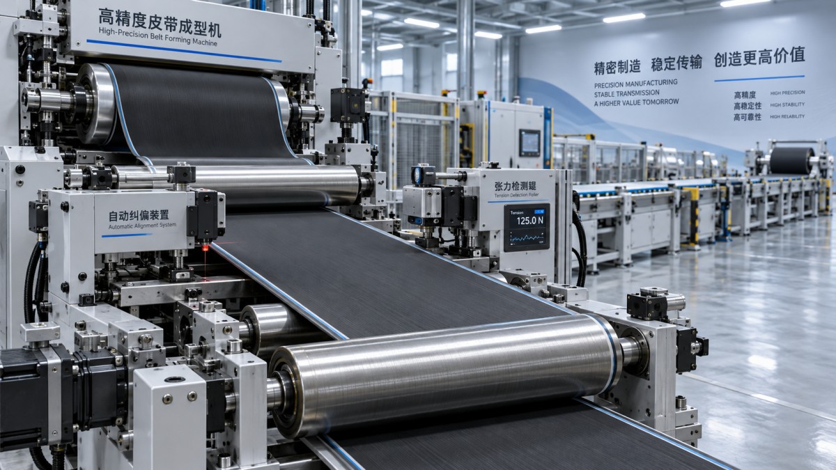
Before adjusting a belt buidling machine, record where wandering begins, its direction, its frequency, and whether it changes with speed, material batch, splice position, or shift.
A belt that drifts immediately after unwinding often points to feed alignment or roll quality. Drift beginning after lamination more often indicates roller geometry or differential tension.
Project leaders should require operators to collect repeatable evidence rather than correcting each event manually. This prevents repeated downtime caused by changing settings without identifying the underlying mechanism.
Separate edge wandering from simple width variation. Wandering means the material centerline moves relative to the machine reference, while width variation may originate from cutting, calendering, or material relaxation.
Also determine whether both edges move together or one edge remains stable. A moving centerline suggests web guiding problems, whereas one unstable edge can indicate skewed rollers or uneven tension.
Review reject records alongside machine speed and production recipes. A clear correlation between errors and a specific product construction usually narrows the investigation faster than a broad mechanical overhaul.
Control Material Feed Before Changing Mechanical Components
Unstable incoming material is a frequent source of apparent machine faults. Variations in roll winding hardness, roll diameter, liner condition, and stored material temperature can alter unwinding behavior significantly.
Confirm that each supply roll is loaded squarely on its shaft and that chucks, expanding shafts, and roll supports hold the roll without side play.
Inspect the unwind brake or drive response during acceleration and deceleration. Excessive braking creates tension peaks, while insufficient braking allows material slack that later becomes lateral movement.
Material should enter the first guiding point at a consistent angle. Even a small side offset at the unwind stand can become a larger edge deviation downstream.
Use a defined incoming-roll acceptance check for high-value production programs. It should include roll width, edge condition, winding quality, core damage, and identification of material batches.
For project schedules, this check is inexpensive compared with commissioning delays. It also provides evidence when a quality issue originates upstream rather than within the belt-building line.
Environmental conditions deserve attention when rubberized textiles or tacky compounds are involved. Temperature changes influence elasticity, adhesion, and release behavior, producing tension changes that controls cannot fully compensate for.
Verify Roller Alignment and Web-Guide Geometry
Mechanical alignment should be treated as a measured condition, not a visual judgment. Roller axes, guide frames, and downstream process stations must reference a common machine centerline.
A roller that is slightly skewed causes the material to migrate toward one side. The effect can become stronger as speed rises or as material tension increases.
Check idler rollers for bearing wear, contamination, damaged surfaces, and unequal rotation resistance. A roller that does not rotate freely can pull one section of the web differently.
Measure parallelism between critical rollers and confirm that the guide actuator has sufficient travel in both directions. A guide operating near its limit cannot correct normal process variation.
Examine pneumatic and hydraulic guide systems for pressure instability, leaks, delayed valve response, and loose mounting hardware. Mechanical looseness can create an oscillation that resembles poor controller tuning.
Cleaning is also an alignment issue in practice. Compound buildup on contact surfaces changes effective roller diameter and can create local traction differences across the belt width.
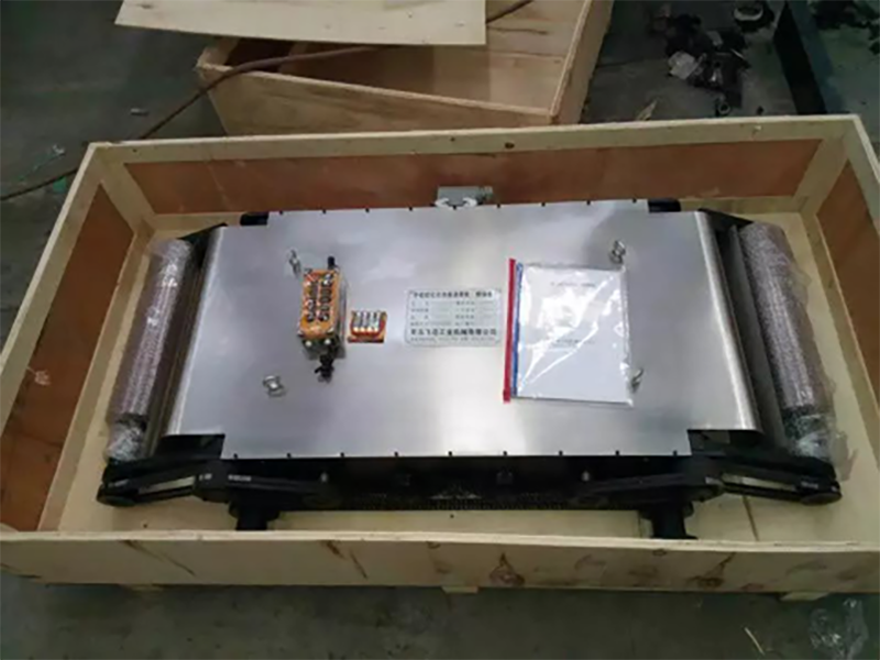
In conveyor belt curing operations, a Platen cleaning device can support stable downstream conditions by removing residue from heating platens before buildup affects production consistency.
Its application should match the press configuration: open daylight between platens should be 230 mm to 350 mm, operating temperature should remain below 60 degrees Celsius, and the power supply is 380V AC three-phase four-wire.
Find the Real Source of Tension Error
Tension errors are often blamed on sensors first, but the sensor may only be reporting a real disturbance. Start by comparing indicated tension with a verified reference measurement.
Calibrate load cells according to the machine documentation and inspect cables, connectors, amplifier settings, and grounding. Electrical noise or damaged shielding can cause fluctuating readings and unstable corrections.
Then assess mechanical contributors: brake drag, drive torque variation, dancer friction, roller bearing condition, and material sticking can all produce real tension variation across the process.
Dancer systems need smooth movement throughout their intended stroke. A dancer that binds, bottoms out, or stays near one end cannot absorb normal changes in web length.
For servo-driven sections, review torque limits, acceleration profiles, and speed synchronization. An aggressive acceleration ramp may be acceptable for one construction but create tension spikes in another.
Do not tune PID values until the mechanical system and sensor signal are stable. Control changes can temporarily hide a fault while making later troubleshooting more difficult.
When tuning is necessary, make one controlled adjustment at a time. Record the parameter, product recipe, speed, measured result, and operator observations for future replication.
Build a Troubleshooting Process That Protects Project Milestones
Project leaders need a defined escalation path because repeated trial-and-error adjustments consume production time without producing reliable lessons for future launches or machine acceptance activities.
First, operators should document the fault with photos, trend data, and the active recipe. Maintenance should then verify material feed, roller condition, alignment, and sensor status.
Engineering should review control logic only after those checks are complete. This sequence limits unnecessary software changes and makes responsibility clear across operations, maintenance, and suppliers.
Set practical acceptance criteria before corrective work begins. Examples include maximum edge deviation, allowable tension variation, stable operation duration, reject rate, and recovery time after a roll change.
Acceptance testing should include normal production speed, startup, stopping, acceleration, and at least one planned material change. A machine that performs only under steady conditions is not fully validated.
Use the results to decide whether the solution is procedural, maintenance-related, or capital-related. A repeated structural issue may justify upgraded guides, improved sensing, or an automated inspection capability.
For refurbished equipment, this discipline is especially valuable. A documented baseline allows teams to confirm that upgrades deliver expected performance and protects the commercial value of the investment.
Reduce Recurrence With Preventive Controls and Clear Ownership
Once the immediate fault is corrected, convert the findings into preventive controls. Otherwise, edge wandering and tension errors commonly return when personnel, materials, or product specifications change.
Create a short inspection standard covering roll loading, guide position, roller cleanliness, pneumatic pressure, sensor zero checks, and critical fastener condition before each production campaign.
Trend edge-guide corrections and tension values by product type. Rising correction demand is an early warning that alignment, material quality, or roller condition is degrading.
Keep spare parts based on actual failure risk, including sensors, guide valves, bearings, brushes, and electrical connectors. Long lead-time components can turn a small defect into a major schedule delay.
Training should focus on diagnosis, not only adjustment. Operators need to know which observations indicate an upstream material problem, a mechanical issue, or a control-loop issue.
Finally, assign ownership for closing corrective actions. Every recurring defect should have a documented cause, accountable owner, completion date, and verification run before it is considered resolved.
Conclusion
Reliable belt building depends on controlling the entire material path, not simply reacting when an edge moves. Feed stability, alignment, measurement integrity, and disciplined control tuning work together.
For project managers, the strongest decision framework is evidence-based: identify the defect pattern, test likely causes in sequence, measure results against acceptance criteria, and standardize successful corrections.
That approach reduces waste and unplanned downtime while giving teams clearer confidence that a belt buidling machine can meet quality targets throughout commissioning and long-term production.
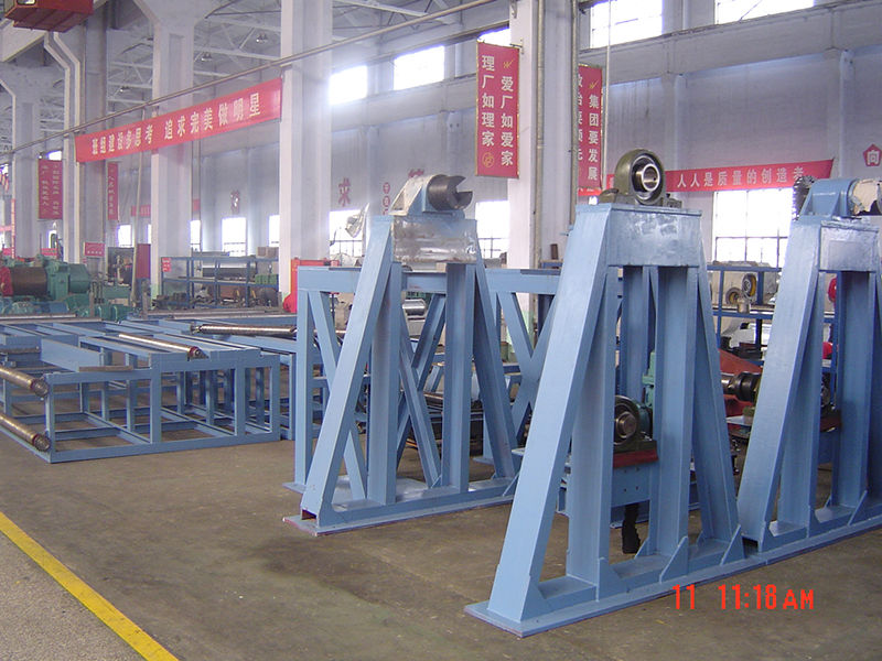
 Green belt building lineJC INDUSTRY manufactures high-quality conveyor belt constant tension laminating machines for fabric rubber conveyor belts. Features PLC control, EPS auto correction, and safety measures. Get factory-direct pricing.
 Platen cleaning deviceEfficient platen cleaning device designed for conveyor belt curing presses. Works in 230mm-350mm daylight with temperature limits below 60℃. Includes brush roller, remote & spare parts.
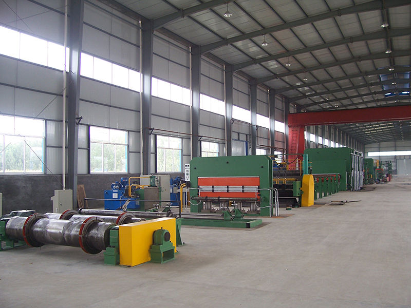
 Steel cord conveyor belt curing press lineProfessional steel cord conveyor belt curing press line for metal processing. Features PLC control, hydraulic systems, and precision tensioning. Ideal for durable conveyor belt manufacturing.