









Send Us A Message
How to test ply alignment on a conveyor belt building machine
How to test ply alignment on a conveyor belt building machine
Misaligned plies can compromise conveyor belt quality, causing uneven loading, edge defects, and premature failure. The useful check is not simply whether the edges look straight. It is whether each reinforcement layer follows the approved construction drawing, stays aligned during lay-up, and remains in position after consolidation, before curing makes correction much harder.
A practical belt buidling machine inspection separates three questions: Is the machine reference correct? Is the incoming ply straight and correctly sized? Does the application process move it? Treating these as separate checks prevents repeated guide adjustments that merely hide a material or tension problem.
Set the acceptance criteria before touching the machine
Use the approved belt construction drawing, process specification, and machine instructions to identify the intended ply position. Some constructions require centered layers; others specify different widths, edge setbacks, or deliberate offsets. Matching every ply edge is not automatically correct.
Confirm the permitted centerline deviation, edge position, ply width, skew, and splice geometry where applicable. There is no single millimeter tolerance suitable for every conveyor belt. If the documentation does not define acceptance limits, obtain an engineering decision rather than adopting a convenient shop-floor number.
Define the inspection condition too: incoming material, freshly placed ply, or consolidated assembly. Measurements taken under different tensions or at different process stages may not be directly comparable. Check individual layers while their edges remain accessible; inspecting only the finished uncured stack can miss buried displacement.
Isolate safely, then establish a trustworthy reference
Before hands-on measurement, isolate the machine using the site’s lockout/tagout procedure. Address electrical power, pneumatic or hydraulic pressure, stored web tension, and components that could rotate, descend, or move unexpectedly. Verify isolation and secure moving assemblies as required. An emergency stop is not an energy-isolation method.
Start from the machine’s documented mechanical datum, not a cover panel, painted mark, or unverified laser line. Check that the table or drum reference, feeding path, and guides relate correctly to that datum. Where a laser or camera provides the centerline, verify its calibration against a physical reference before relying on its display.
Use calibrated measuring tools with resolution appropriate to the specified tolerance. A straightedge, suitable rule, square, or approved noncontact system may be sufficient, depending on access and construction. Avoid pressing into soft uncured rubber or pulling the ply sideways to make a measurement easier.
Measure both edges, not just the convenient one
Mark inspection stations on the production record: near the beginning, at intermediate positions, near the end, and around relevant splices or transitions. Station spacing should follow the control plan and the likelihood of local movement. A beginning-and-end check alone can miss a temporary wander between them.
At each station, measure the left and right ply-edge coordinates perpendicular to the same verified reference. Use a consistent signed coordinate system. Calculate the ply center as (left-edge coordinate + right-edge coordinate) / 2, then subtract the specified target center coordinate to obtain centerline offset. Ply width is the right-edge coordinate minus the left-edge coordinate.
Recording width alongside offset matters. One edge moving outward could indicate width variation rather than lateral displacement. If both edges shift by approximately the same amount while width remains stable, lateral movement is more likely.
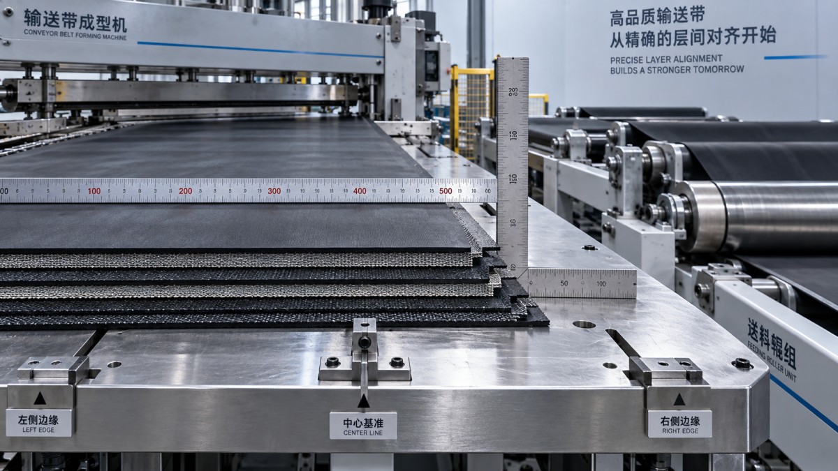
Compare each layer with its own drawing position and with the intended relationship to adjacent layers. Do not use the preceding ply as the only reference: several layers can be neatly aligned with one another while the entire stack is displaced from the machine centerline.
Changing offset along the build indicates drift or skew. The difference between offsets at two stations describes lateral change over the measured distance, but does not by itself prove the cause. Where reinforcement orientation is specified, inspect cord or fabric direction separately; straight edges do not guarantee correct internal orientation.
Check what changes during feeding and consolidation
A static alignment check cannot establish whether the ply tracks correctly under production conditions. After removing tools and personnel, restoring guards, and releasing isolation through the approved procedure, conduct an authorized trial. Observe from outside the hazard zone using fixed sensors, cameras, or protected viewing positions. Never reach toward moving material to check an edge.
Compare placement before and after consolidation at corresponding stations, repeating isolation before further hands-on measurement. If the ply arrives correctly but moves during pressing or stitching, investigate roller alignment, pressure distribution, surface condition, and tension balance. Steering the supply guide may otherwise compensate for one defect while introducing another.
- Constant offset: check datum selection, guide settings, and sensor zero.
- Progressive drift: inspect unwind alignment, roll condition, tension balance, and feed-path squareness.
- Sudden displacement: examine splice passage, roll changes, tension disturbances, and unintended guide movement.
- Movement after consolidation: check application mechanics and material condition before changing upstream settings.
These patterns guide troubleshooting; they are not diagnoses. Change one controlled variable at a time and repeat the relevant measurements.
Apply the same evidence standard to new and refurbished equipment
JC INDUSTRY combines machinery manufacture with installation, commissioning, and refurbishment services. Its Used Machinery and Equipment Recycling Center was established in 2015, and the company states a 24-month warranty for new and used equipment. Warranty coverage, however, does not replace an alignment acceptance trial using the intended material, construction, and operating conditions.
Related equipment illustrates why machine capability and product acceptance must remain separate. JC INDUSTRY’s Tyre building macine lists servo-controlled functions and remote diagnostics for precision tire manufacturing. Those functions can support controlled positioning and troubleshooting, but tire-building specifications are not conveyor-belt alignment tolerances. Confirm application suitability with engineering rather than transferring settings between processes.
Release the build on recorded results
Record the machine identification, recipe, material roll, ply number, measurement stations, reference datum, tool identification, process condition, and actual readings. Include adjustments and repeat-test results. Photographs help explain a defect, but should not replace measurements.
If any reading exceeds the approved limit, hold the affected build for disposition before curing. After correction, recheck the affected layers and locations, not merely the easiest visible edge. Release should follow the documented acceptance criteria and authorization process—not the judgment that the stack now looks straight.