










Send Us A Message
How to check blade-area guarding on a hydraulic bale cutter
A loose panel or widened feed opening on a hydraulic bale cutter can expose someone to the blade, hold-down mechanism, or crushing zone. A guard that looks complete may still allow access around its edges, and a closed door does not prove that its interlock works. Start by checking physical integrity and access prevention under verified energy isolation, then have authorized personnel test safety functions using the manufacturer’s procedure.
Remove the machine from service when guarding is missing, insecure, bypassed, or unable to prevent hazardous access. Do not reach toward the blade to judge clearance, and do not run a cutting cycle with a guard open to “see what happens.” Inspection must distinguish between checks that require lockout and controlled functional tests that require power.
Establish the inspection boundary before approaching the blade
Identify the machine model, serial number, guard arrangement, and available operating and maintenance instructions. Confirm whether the installation matches the documented configuration. Refurbished equipment deserves particular attention where replacement panels, altered feed tables, or changed controls may have affected the original safeguarding.
Walk around the machine from outside the safeguarded area. Include the loading face, discharge side, rear access, underside, and any adjacent platform. A barrier that protects the normal operating position may leave the same blade reachable from a maintenance aisle or through an opening behind the frame.
Gather the approved guarding drawings, previous defect records, a light, and suitable measuring equipment. Access-distance assessment may require specified test probes and safety-distance references rather than a tape measure alone. Where applicable, standards such as ISO 13857 can inform reach assessment, but the relevant edition, machine-specific requirements, and local obligations must be confirmed.
Isolate energy for the physical examination
Before removing covers, touching guarding near the danger zone, or entering an access area, follow the machine-specific lockout/tagout procedure. An emergency stop, selector switch, or stopped pump is not energy isolation.
- Shut down normally, identify every relevant energy source, and apply the required isolation devices and personal locks.
- Control stored hydraulic energy, including accumulators and trapped pressure, according to the manufacturer’s instructions. Do not loosen hydraulic fittings to release pressure.
- Secure the blade, ram, hold-down, and other gravity-loaded components with approved mechanical restraints wherever required. Do not rely on hydraulic pressure to hold them up.
- Verify isolation using the prescribed method, including an attempted start where specified and checks appropriate to the hydraulic system. Return controls to their safe state afterward.
A zero reading on one pressure gauge does not prove that every circuit is depressurized. Where isolation points, accumulator arrangements, or blocking locations are unclear, stop the inspection until a competent person establishes a safe procedure.
Inspect the barrier, then trace every possible access route
With hazardous energy controlled, examine the entire guard rather than only its front surface. Material trapped behind a panel can bend it outward, while repeated loading impacts can damage hinges or enlarge fastener holes without leaving an obvious opening from the operator’s viewpoint.
- Panels and mesh: Look for cracks, broken welds, corrosion, missing sections, distortion, and unauthorized cutouts.
- Mountings: Check for missing or loose fasteners, damaged threads, worn hinges, insecure frames, and latches that do not engage fully.
- Fixed-guard retention: Confirm that removal requires tools where specified and that the original fastening arrangement has not been replaced by an unsuitable quick-release arrangement.
- Edges and interfaces: Examine gaps between guards, around hydraulic lines, beside the feed table, and beneath the enclosure.
- Containment: Where the guard also contains fragments or ejected material, check its material and condition against the approved specification. Preventing reach alone may not satisfy that function.
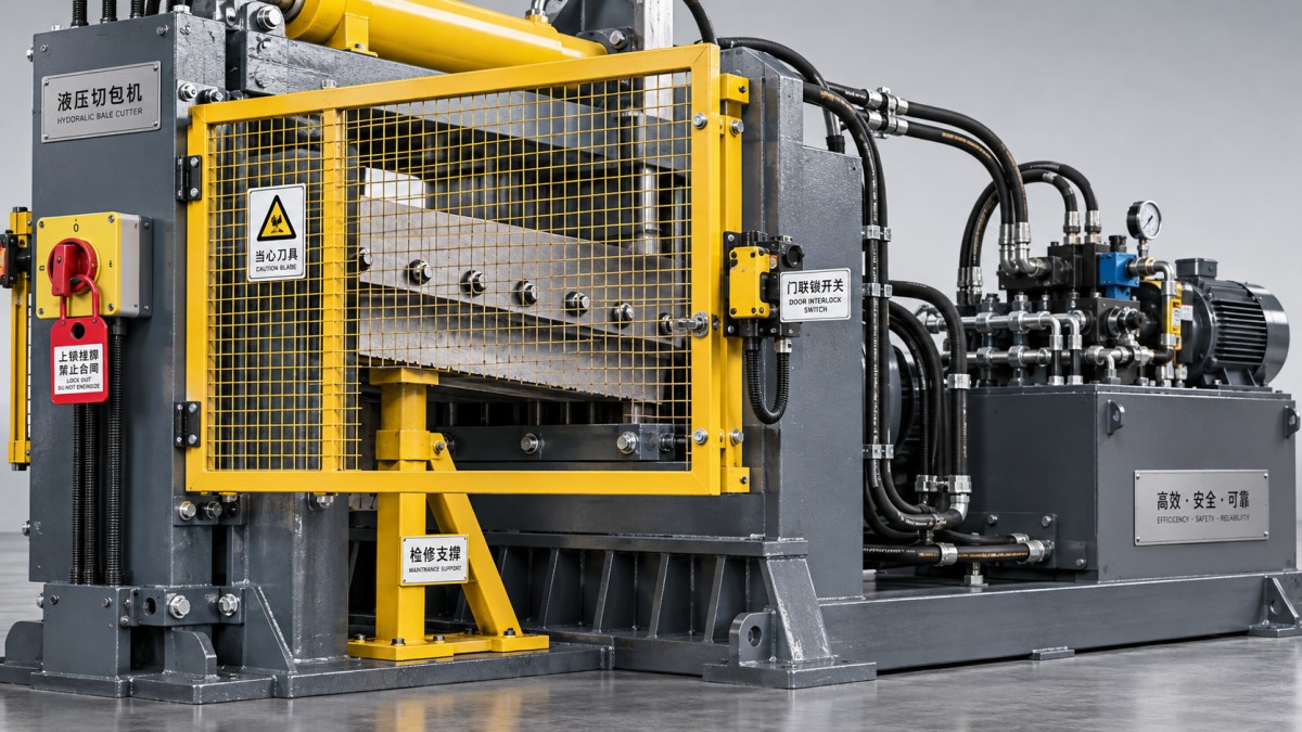
Measure suspect openings and their distance from the nearest hazardous movement using the approved assessment method. Record both dimensions and the approach direction. Whether an opening permits access depends on its shape, size, distance from the hazard, and whether someone can reach over, under, around, or through it. There is no single acceptable gap size for every installation.
Pay close attention to feed and discharge openings. The material passing through an opening is not a dependable barrier: an incomplete load, smaller bale, or cleared chute can expose a path to the blade. Do not validate an opening by inserting a hand, arm, or improvised object toward the cutting zone.
Also consider foreseeable tasks outside normal cutting: removing wrapping, clearing a jam, retrieving offcuts, and cleaning beneath the blade. If a routine task encourages reaching past the guard, record it as a safeguarding or work-method issue rather than simply attributing it to operator behavior.
Test interlocks without exposing anyone to motion
Physical inspection cannot establish whether the safety circuit performs correctly. After the isolated examination, restore the machine only through the approved restoration process. Authorized personnel should conduct functional testing with everyone outside the danger zone, guards appropriately installed, and the test area controlled.
Use the manufacturer’s test sequence and acceptance criteria. Depending on the design, this should establish whether an open access guard prevents hazardous motion from starting, whether opening a guard produces the specified safe response, and whether closing it alone causes an unexpected restart. Resetting a safety function should not itself initiate hazardous motion.
Do not open a guard during hazardous movement unless the validated test procedure explicitly provides a safe method. Never bridge a switch, use a spare actuator, or defeat a sensor to complete the inspection. Misalignment, intermittent operation, damaged cables, and evidence of bypassing require investigation, not adjustment until the machine merely “runs again.”
Where motion or stored energy remains hazardous after a stop command, access may require guard locking until a safe condition exists. A visible stop is not proof of adequate stopping performance. Safety-distance calculations, stopping-time measurements, guard-locking behavior, and safety-control validation belong with competent personnel using suitable methods and equipment.
Check emergency-stop operation separately as prescribed. A functioning emergency stop does not compensate for an inadequate blade guard or failed interlock.
Decide whether to release, repair, or escalate
The inspection record should identify the machine, guard location, measured openings, photographs, test method, acceptance basis, defects, and responsible sign-off. After repair, repeat the affected physical checks and safety-function tests. Replacing a hinge or switch does not by itself demonstrate that protection has been restored.
Keep verification specific to the machine
In a tire-production facility, inspection records may also cover equipment such as a Balance testing machine, which performs dynamic balancing and ovality detection. Its process-testing results are separate from safeguarding verification and cannot establish that a cutter’s blade area is safe.
Set inspection frequency from the manufacturer’s instructions, risk assessment, usage, and damage history. Include operator pre-use observations, scheduled detailed inspections, and additional checks after impacts, jams, relocation, or modifications. Release the cutter only when identified defects are closed and the required verification demonstrates that hazardous access is prevented.