









Send Us A Message
Why does a vulcanizing press lose pressure during the cure?
A vulcanizing press loses pressure during the cure when the clamping circuit cannot retain hydraulic pressure, cannot replenish it as designed, or is reporting pressure incorrectly. Internal valve leakage, cylinder seal bypass, and failed automatic top-up are stronger suspects than the pump when the machine reaches its setpoint normally but cannot hold it.
The decisive distinction is whether the machine is losing actual clamping force or only showing a lower pressure reading. Establish which circuit is dropping and exactly when the drop begins before replacing components. A supply-line gauge, a clamping-cylinder transducer, and a tire bladder pressure signal describe different conditions.
Confirm what pressure is being lost
Use the hydraulic schematic and machine operating sequence to identify the affected measurement point. On a hydraulic clamping press, the pump may unload after closing while a check valve or pressure-holding valve traps pressure at the cylinder. A falling pump-line gauge can therefore be normal while cylinder pressure remains stable.
On tire curing equipment, bladder steam, hot water, or nitrogen pressure is separate from mold-clamping pressure. A curing-medium pressure loss requires investigation of its own valves, piping, seals, and supply controls. It should not automatically trigger hydraulic pump troubleshooting. Mechanically locked machines also require interpretation of lock position and load transfer rather than hydraulic pressure alone.
Where the machine provides suitable test points, compare the displayed value with a calibrated gauge connected to the same pressure zone. Account for gauge accuracy and response time. Agreement confirms that the pressure change is real; disagreement directs attention toward the transducer, wiring, scaling, or measurement location.
Make the investigation safe before testing
A closed press can retain hydraulic, pneumatic, and thermal energy after electrical power is disconnected. Accumulators and isolated cylinder chambers can remain pressurized even when another gauge reads zero.
Before installing instruments or opening any connection, follow the machine’s lockout procedure, isolate energy sources, discharge stored pressure through approved provisions, and verify the relevant circuit is depressurized. Use manufacturer-specified mechanical supports wherever platen movement could create a crushing hazard. Never loosen a fitting to check for pressure or search for a pinhole leak by hand.
Powered observations require a controlled test with guards and interlocks operating, personnel outside hazardous areas, and instruments rated for the expected pressure and temperature. Do not bypass safety functions, block relief paths, or improvise shutoff arrangements to isolate a suspected leak.
Use the pressure pattern to narrow the fault
Record cylinder pressure alongside oil temperature, platen position, pump operation, and top-up valve commands. If available, include the pressure setpoint and raw transducer signal. A trend through closing, pressure build-up, and cure hold is more useful than a single low-pressure reading.
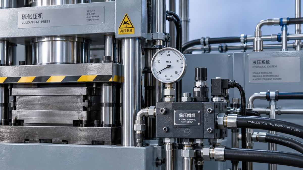
A small pressure dip is not automatically a fault. Some presses deliberately replenish pressure between defined limits. The meaningful questions are whether pressure remains within the validated process window, whether recovery occurs correctly, and whether replenishment becomes more frequent under comparable conditions.
Find where the trapped pressure is escaping
Pressure-holding valves and pilot circuits
A pilot-operated check valve or dedicated holding valve can leak across its seat because of contamination, wear, or damage. Oil then escapes from the trapped cylinder volume even without a visible external leak.
The valve may also be mechanically sound but incorrectly piloted open. Residual pilot pressure, a leaking directional valve, or a sequencing error can prevent reliable closure. Replacing the holding valve without checking its pilot circuit can leave the original fault unchanged.
Use the manufacturer’s designated pressure points and leakage-test procedure to separate these possibilities. An energized coil does not prove that a valve has shifted, and a de-energized coil does not prove that a hydraulic seat is sealing.
Cylinder seals and external leakage
Piston seal bypass allows oil to cross between cylinder chambers. It may cause pressure decay, platen creep, or both, depending on the circuit and mechanical constraints. A stationary platen does not rule it out: mold contact or a mechanical restraint can limit visible movement while pressure falls.
Check accessible hoses, fittings, manifolds, and rod seals for external leakage without entering the danger zone. If no external leak explains the loss, cylinder bypass remains a possibility, but pressure decay alone cannot distinguish it from valve leakage. Cylinder isolation tests must follow the approved procedure; improvised port blocking can create trapped pressure or unexpected force.
Relief valves and shared return paths
A relief valve that fails to seat, a leaking unloading valve, or an unintended connection to a lower-pressure circuit can provide an escape path. Their relevance depends on where they sit relative to the holding valve. A pump-side relief valve cannot drain a cylinder chamber that is correctly isolated from it.
Trace the actual trapped-pressure boundary on the schematic before selecting components for testing. Do not raise the relief setting to conceal pressure loss: this can overload components without correcting the leakage path.
Check replenishment before blaming the pump
If the press achieves closing pressure but fails to restore pressure during cure, inspect the automatic top-up sequence. The controller may not recognize the low-pressure threshold, the replenishment valve may not open, or the pump may remain unloaded.
Compare the pressure reading, replenishment request, electrical output, and hydraulic response. A missing request suggests a signal, setpoint, or sequence issue. A valid command without pressure recovery points toward valve operation or available hydraulic supply.
Pump wear becomes more credible when the machine also builds pressure slowly or cannot deliver the required flow at working pressure, particularly with warm oil. Pump condition should be assessed using specified pressure, flow, and case-drain tests where applicable—not inferred solely from a falling hold-pressure gauge.
Where an accumulator supports pressure holding, loss of usable capacity can cause shorter top-up intervals or deeper pressure dips. Check its isolation arrangement, charging path, and precharge according to the manufacturer’s procedure. Precharge measurement requires hydraulic-side depressurization and appropriate charging equipment; it must not be guessed from operating pressure.
Separate heat-related effects from leakage
Pressure depends on trapped oil volume, temperature, system compliance, and cylinder position. Mold or rubber movement under load can increase the volume that the hydraulic circuit must supply. If replenishment is absent or delayed, pressure can fall without a major component leak.
Thermal effects require careful interpretation. Heating oil in a confined volume can raise pressure, while cooling can reduce it. At the same time, warmer oil has lower viscosity and can leak more readily through worn clearances. “It drops when hot” therefore supports further testing, not an automatic seal diagnosis.
Compare equivalent cure conditions using the specified oil grade and a stabilized operating temperature. Check for aeration, abnormal foaming, and oil-level problems. Entrained air increases compressibility and can make pressure build-up and recovery less predictable.
Verify the repair through a complete cure
A successful closing stroke does not prove that pressure holding has been restored. Repeat the operating conditions associated with the fault and record pressure, temperature, replenishment behavior, and platen position throughout the hold period.
Acceptance should follow the machine specification and validated curing process rather than a universal allowable pressure-drop figure. Frequent top-up can conceal continuing leakage even when displayed pressure stays within limits. Document the confirmed escape path or control fault, the corrective work, and the post-repair trend. Products exposed to inadequate clamping conditions should be evaluated under the site’s quality procedure before release.