










Send Us A Message
Why does bead placement drift on a tyre building machine?
Bead placement drift usually indicates a repeatability problem somewhere between the bead setter, building drum, guides, sensors, and control system.
For after-sales maintenance personnel, the fastest solution is identifying when drift begins, whether it affects one side, and whether it follows the machine or tooling.
Do not begin by changing the bead position setting. First confirm the actual movement pattern, because mechanical wear and unstable air pressure often imitate incorrect parameter values.
What bead placement drift usually indicates
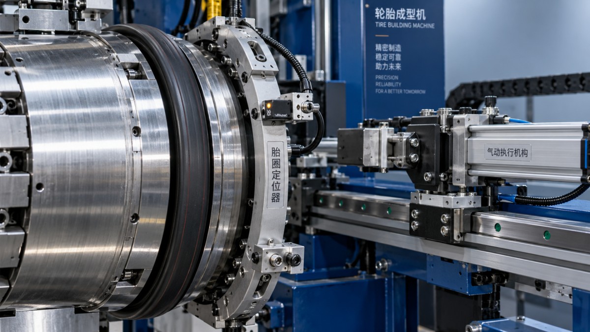
Bead drift means the bead assembly no longer reaches its commanded axial or radial position consistently during tyre building operations.
Some machines show gradual movement over several cycles, while others produce sudden offset after tool changes, maintenance, or production speed increases.
A constant offset on both sides often suggests an incorrect reference, drum position, or recipe value requiring verification.
A changing offset between cycles usually points toward looseness, contamination, air instability, sensor noise, or inconsistent bead handling.
If only one bead drifts, investigate that side independently before adjusting common machine parameters or replacing central control components.
When drift increases with machine speed, acceleration, or production temperature, dynamic mechanical behavior becomes more likely than a simple calibration error.
Check the symptom before opening the machine
Record the actual bead position from several consecutive cycles using the same tyre specification, speed, pressure, and operator settings.
Measure both left and right bead positions relative to a fixed drum reference rather than relying only on the machine display.
Write down whether the error is axial, radial, angular, or rotational, because each pattern leads toward different causes.
Repeat the check after changing the recipe, bead size, or production speed to determine whether the fault follows the process conditions.
Inspect rejected tyres for a consistent circumferential error or a localized defect, since these findings provide useful clues about timing and movement.
Compare the machine’s commanded position with its actual position during slow manual movement, automatic cycling, and normal production operation.
This evidence prevents maintenance teams from correcting a visible symptom while leaving the original source of drift untouched.
Inspect bead setter alignment and mechanical condition
The bead setter must remain parallel and concentric with the building drum throughout its complete travel range.
Check mounting bolts, linear guide blocks, shafts, brackets, cylinders, and end stops for looseness, deformation, wear, or abnormal movement.
Even slight play in a guide can create a larger positioning error when the bead setter reverses direction or accelerates.
Move the assembly manually with power isolated and compare resistance on both sides of the travel path.
Uneven resistance may indicate damaged guides, contaminated rails, bent shafts, incorrect lubrication, or a mounting surface that has shifted.
Verify that mechanical stops contact evenly and that no accumulated rubber dust prevents the setter from reaching its reference position.
Check the building drum for runout, damaged shoulders, incorrect width, or poor concentricity after maintenance or drum replacement.
A drum that rotates eccentrically can make accurate bead placement appear unstable even when the setter itself is correctly aligned.
Examine bead guides, clamps, and handling surfaces
Worn bead guides can allow the bead to rotate, tilt, or move sideways before it reaches the building drum.
Inspect guide surfaces for grooves, sharp edges, rubber deposits, missing fasteners, and uneven wear between the operating sides.
Confirm that bead clamps close evenly and hold the bead securely during transfer, positioning, and release.
If a clamp releases too early, the bead may shift under its own tension before the control system records completion.
Check whether different bead specifications require different guide inserts, clamp pressures, or mechanical stops.
Using a worn guide with a smaller bead can produce intermittent drift, while a tight guide may distort the bead and create placement variation.
Clean all contact surfaces according to the machine manufacturer’s procedure, avoiding lubricants that can reduce grip or contaminate rubber components.
After cleaning, run slow cycles and observe whether the bead remains stable during approach, clamping, transfer, and release.
Verify pneumatic pressure and cylinder movement
Unstable pneumatic pressure is a common cause of bead setter movement that changes from cycle to cycle.
Check the main pressure, local regulator setting, filter condition, air preparation unit, and pressure at the actuator during movement.
Static pressure can appear normal while a restricted hose, undersized valve, or leaking fitting causes pressure loss during operation.
Observe cylinder motion for hesitation, bouncing, overshoot, uneven speed, or delayed stopping near the target position.
Inspect seals and rod surfaces for leakage, contamination, corrosion, or mechanical damage that could produce inconsistent force.
Verify flow-control valves and cushion settings after replacing cylinders, valves, or pneumatic tubing.
Excessive actuator speed may cause impact against the stop, while insufficient speed may allow the bead to settle differently each cycle.
Record pressure during automatic cycling rather than checking only the gauge when the machine is idle.
Check sensors, references, and control timing
Position sensors must be mounted securely, aligned correctly, and protected from rubber dust, vibration, and accidental contact.
Check sensor brackets for movement and confirm that the sensing distance remains within the supplier’s specified operating range.
Review encoder feedback, proximity switches, cylinder sensors, and home-position signals for intermittent loss or unstable switching.
A sensor that changes state late may cause the controller to release the bead setter before the mechanical position is stable.
Use the diagnostic screen or controller monitoring function to compare commanded position, feedback position, and completion signals.
Inspect cables, connectors, terminal blocks, and grounding points, especially where vibration or repeated movement can damage wiring.
Confirm that the recipe uses the correct drum width, bead size, machine station, and compensation values for the current tyre specification.
Restore parameter backups before making changes, and record every adjustment so the previous condition can be recovered if necessary.
Do not compensate for a loose guide by changing sensor offsets, because the machine may then fail when the guide is repaired.
A practical troubleshooting sequence for maintenance teams
Start with a controlled baseline: clean the working area, confirm air pressure, install the correct tooling, and load a verified recipe.
Next, measure the machine reference and bead position at low speed across at least ten consecutive cycles.
If the error repeats in the same direction, inspect alignment, stops, drum width, and reference settings before testing sensors.
If the error changes randomly, focus on looseness, pneumatic pressure, actuator behavior, sensor signals, and electrical connections.
Swap a suspect sensor or guide with a known-good component only when the replacement is suitable and the change can be tracked.
If the fault moves with the component, the component is probably responsible; if it remains in place, continue toward the machine reference.
After each correction, repeat the same measurement method and compare results under identical operating conditions.
Use production speed only after low-speed positioning is stable, because high-speed testing can hide the original mechanical cause.
How to prevent the problem from returning
Create a maintenance record showing bead position, pressure readings, sensor status, tooling condition, and the number of cycles tested.
Set inspection intervals for guide wear, fastener torque, drum runout, cylinder leakage, and sensor mounting security.
Train operators to report gradual drift early rather than correcting it repeatedly through recipe offsets.
Keep reference tooling and calibration gauges clearly identified, clean, and protected from accidental damage during production changes.
When upgrading equipment or adding digital monitoring, stable communication between electronic control, sensors, and mechanical actuators improves fault tracing.
For plants managing several polymer and rubber processes, reliable upstream equipment also supports consistent material preparation and production scheduling.
For example, a Pp pe abs ps sheet extruder line can provide stable sheet extrusion for applications requiring controlled polymer processing.
When to request specialist service support
Contact the equipment supplier when drift remains after mechanical inspection, pressure verification, sensor testing, and recipe confirmation.
Specialist support is especially useful when the error appears only at production speed or after software, servo, or encoder changes.
Provide the machine model, tyre specification, measured offsets, cycle videos, alarm history, pressure readings, and recent maintenance details.
This information allows service engineers to separate tooling problems from control problems before recommending replacement parts or parameter changes.
JC INDUSTRY combines equipment design, installation, commissioning, consultation, and refurbishment support for machinery users managing long-term production needs.
Its service approach can also help maintenance teams evaluate whether an aging machine requires targeted upgrades or broader modernization.
Conclusion
Bead placement drift is usually a repeatability failure involving alignment, wear, pressure, sensing, timing, or tooling condition.
The most reliable diagnosis begins by measuring the drift pattern and separating constant offset from cycle-to-cycle variation.
After-sales personnel should verify mechanical accuracy first, then check pneumatic behavior, sensor feedback, control timing, and recipe data.
Once the physical cause is corrected, recalibrate references and validate several consecutive cycles at both low and production speed.
This method reduces scrap, shortens troubleshooting time, and restores dependable bead positioning without relying on temporary parameter compensation.