










Send Us A Message
Why does an injection moulding press produce flash at the seam?
Why does an injection moulding press produce flash at the seam?
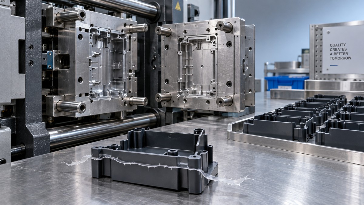
A thin ridge of unwanted plastic along a mould seam can mean extra trimming, rejected parts and costly downtime. When an injection moulding press produces flash at the parting line, the cause may be insufficient clamping force, excessive cavity pressure, worn mould surfaces or poor alignment—not simply a machine setting that needs turning up. Finding the source before making adjustments protects both the mould and production quality.
Flash forms when molten polymer enters a gap that should remain closed. Either the mould already has a local gap, or pressure opens one during filling or packing. That distinction determines whether the remedy belongs in the process settings, the clamping system or the toolroom.
Read the flash pattern before changing settings
Keep the last acceptable part and the first defective part, noting the cavity number and machine conditions. The location and timing of the defect often narrow the investigation faster than repeated parameter changes.
- Flash around much of the perimeter: investigate cavity pressure, available clamping force and whether the mould closes fully.
- Flash at one corner or one cavity: suspect damaged sealing surfaces, uneven support, alignment problems or an unbalanced filling pattern.
- Flash appearing after warm-up: check actual melt and mould temperatures, thermal movement and process drift.
- Flash beginning after a mould change: review mounting, mould-height adjustment, platen cleanliness and clamp setup.
These are diagnostic clues, not proof. A restricted gate, for example, can drive operators to raise pressure until a weak section of the parting line starts leaking.
Is the mould being forced open?
The opening load depends on cavity pressure acting over the projected area of the moulded parts and relevant runners, viewed in the clamping direction. A useful engineering starting point is:
Required clamp force ≈ projected area × cavity pressure
Use consistent units and a suitable engineering margin. Cavity pressure is not interchangeable with the hydraulic pressure displayed on the machine. Where cavity sensors are unavailable, pressure estimates need validation against the material, geometry and established process.
The press’s rated tonnage does not confirm the force actually delivered to the mould. Depending on machine design, incorrect toggle adjustment, hydraulic faults, uneven tie-bar loading or platen deflection can affect closure. Maintenance personnel should verify actual clamp performance using the manufacturer’s procedures.
Do not automatically increase tonnage to the maximum. Excessive force can accelerate tool wear, distort components and reduce effective venting. If a small, authorised increase removes widespread flash, it suggests insufficient closing force relative to cavity load—but does not establish why that load became excessive.
Separate filling problems from packing problems
Flash can develop during fast filling or after the cavity is substantially full. The correction differs. Under an approved process-development procedure, a qualified technician can compare controlled fill-only samples with normally packed parts. This helps identify the stage at which leakage begins.
If flash is already present during filling, investigate injection velocity near the end of fill, the velocity-to-pressure transfer position and restrictions that demand excessive pressure. Transferring too late can create a pressure spike as the cavity becomes full. Slowing the entire injection stroke may hide the symptom while introducing hesitation or short shots; a targeted velocity-profile adjustment is usually more informative.
If filling is clean but packing introduces flash, review holding pressure and the transfer point. Holding time also matters while the gate remains open. Reducing packing indiscriminately can produce sink marks, voids or dimensional variation, so assess part weight and critical dimensions alongside seam appearance.
Check actual temperatures rather than relying only on setpoints. Hotter material generally flows more readily into small gaps, although lowering temperature can increase filling pressure. A changed resin grade, regrind proportion or preparation condition may also change flow behaviour. Restore the validated material and temperature conditions before compensating elsewhere.
When the seam itself needs attention
Persistent flash in exactly the same location points towards a mechanical inspection, particularly when settings remain stable. The machined steel interfaces matter as much as the press controls: a damaged shut-off cannot reliably be corrected through software.
With the machine isolated and the mould secured under site safety procedures, qualified personnel should check for trapped polymer, damaged parting-line lands, worn guide components, insert movement and inadequate support. Approved contact-checking methods can reveal uneven seating that is difficult to see directly.
Vents deserve particular care. A vent cut too deep can become a flash path; blocked vents can trap gas, complicate filling and encourage pressure increases. Vent dimensions must suit the polymer and tool design. Do not deepen vents or grind sealing surfaces as an improvised production-floor repair.
Make the correction repeatable
Record the baseline before testing: material batch, actual temperatures, fill time, transfer position, cushion, pressure settings, clamp setting and affected cavities. Change one variable at a time within approved limits. Allow the process to stabilise, then check more than whether the ridge has disappeared. Weight, dimensions and other defects must remain acceptable.
Recipe control and operation monitoring help preserve that baseline across shifts. In adjacent tyre-production equipment, JC INDUSTRY’s Inner liner cutting line uses a 1768 AB series PLC and Ethernet bus network, with parameter memory and operation monitoring. Its servo-controlled cutting and 85°–90° cutting-angle range serve a different process; it is not a remedy for mould flash. The relevant connection is disciplined control of settings and operating conditions.
When an injection moulding press still flashes within its validated processing window, request a joint machine-and-tool assessment rather than continuing to raise clamp force. JC INDUSTRY combines machinery manufacture with installation, commissioning and consultation, including rubber and plastics equipment. Its recycling centre, established in 2015, also refurbishes and upgrades used machinery, with a stated 24-month warranty for both new and used equipment.
For any refurbished press, warranty coverage should sit alongside documented checks of clamp performance, platen condition and control repeatability. Bring the service team a flash-location map, retained samples and process records: those details help distinguish a repairable tool defect from a machine fault or a press that is unsuitable for the mould’s operating requirements.